

 24/06/2026 20:21:34
 Translated from Spanish automatically
Response on the intensity wave in electrotherapy
In response to a colleague who raises:
"
I do not understand well how when measuring the voltage in a resistance you can speak of an intensity wave (if voltage is measured).
"
Answer
First .-- Oscilloscopes always pick up and measure voltage or potential difference, and do not measure currents.
Second .-- With oscilloscope measurements and formulas, the intensity can be calculated.
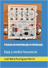
Suppose a 12 V DC battery (not alternating or pulsed to facilitate calculations). the battery charged with its 12 V and without connecting to anything, its terminals are measured with an oscilloscope, and this says that the 12 V are ready to be used, but no energy circulates; Consequently, it is not possible to measure the intensity or calculate it (Figures 1 and 2).
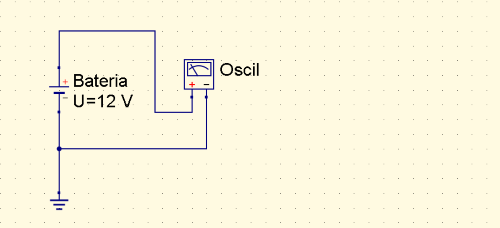
Fig 1.-- Battery without charge measured with oscilloscope.
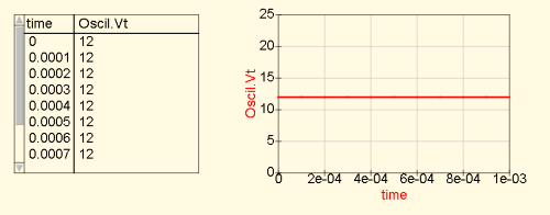
Fig 2.- 12 V results in numerical value and graphical representation.
If now the battery discharges its energy on a charge (let's put a resistance of about 2.000 Ohm) let's see what happens
Fig 3.- 12 V results; equal to the measurement without load.
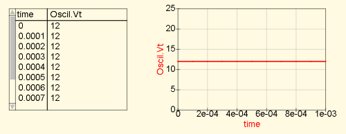
Fig 4.- 12 V results in numerical value and graphical representation with load.
But now you can apply Ohm's Law and calculate the intensity.
V / R = I >>> 12 / 2.000 = 0,006 amps (6 mA)
To demonstrate this, an ammeter is interposed in one of the conductors that go to the charge and values [V] of the battery and the ammeter are measured (figures 5 and 6)
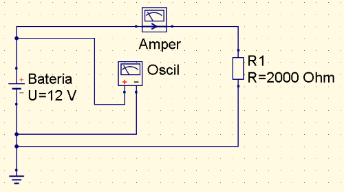
Fig 5.- An ammeter is interposed between the battery and the load to know the intensity.
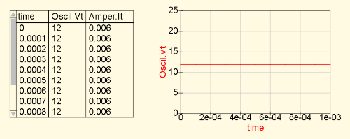
Fig 6.- Results of 12 V on the battery and 0,006 A of intensity.
If now a low value resistance is added (in this case R2 = 1 Ohm) on the path that goes to the charge R1, an oscilloscope is connected to see the potential difference between its extremes and values are presented, we will have the following results : figures 7 and 8
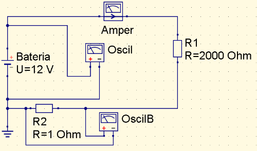
Fig 7.- R2 is interleaved with oscilloscope B to see what happens between the terminals of R2.
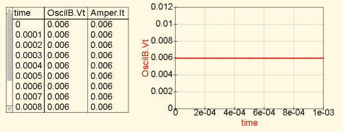
Fig 8.- 6 mV results on oscilloscope B and continues to run 6 mA through the ammeter.
This small resistance [R2] minimally influences the load and the results of the circuit, but the waveforms obtained in this resistance represent the behavior of the current and not the behavior of the battery supply voltage.
In this case, as we work with direct current, a horizontal straight line is always represented, but when the currents are variable, alternating or pulsed: in the general voltage oscilloscope [Oscil] a certain shape is represented, but in the oscilloscope of the interposed resistance [OscilB] for the intensity, other different shapes are drawn.
The problem with this resistance [R2] is that the smaller its value, the weaker the waves and the greater the difficulties of calculation.
I recommend between 5 and 10 Ohm, which interfere with the circuit very little and the waves are easier to measure and cleaner.
Also note that if you read figure 8 carefully, since R2 is 1 Ohm, the number of the voltage value is the same as the current value of the circuit, which induces the voltage to be converted into a direct reading of intensity. This (let's say trick) is used in many measurement systems to convert the voltage value directly into the current value.
As a last test, the charge [R] is removed and it is observed what happens in the general current of the circuit [Amper] and in the oscilloscope B of R2. Figures 9 and 10
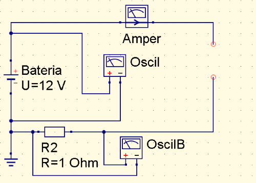
Fig 9.- The R1 charge is removed to analyze OscillaB and read the overall current of the circuit.
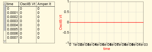
Fig 10.- The R1 charge is removed to analyze OscillaB and read the overall current of the circuit.
By eliminating the charge, it works in a vacuum and it is like going back to what is represented in figures 1 and 2. Although the battery continues to offer its 12 V, it cannot apply it and no intensity passes nor does a potential difference appear at the ends of the battery. resistance [R2].
So when there is no charge, the source voltage can be measured, but the voltage across R2 is zero because no power is circulating. This is why it is called "intensity resistance".
It is the typical example of TENS when they are measured with an
oscilloscope and the electrodes in the air, a type of waves are drawn
that have nothing to do with those that are drawn when applied to the
patient or on an artificial charge that simulates the patient. A TENS
with the electrodes in the air does not draw the intensity waves
either, but the voltage waves (although very altered). See figures 11
to 14.
I hope I have explained the subject in sufficient detail and that you have understood me.
Observe, compare and analyze the following figures about the voltage and intensity wave in a TENS.
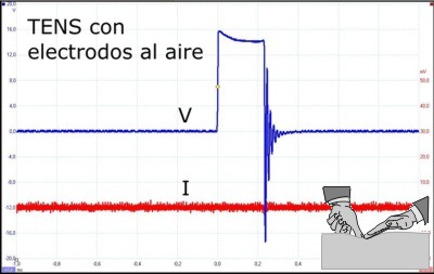
Fig 11.-- TENS with air electrodes.
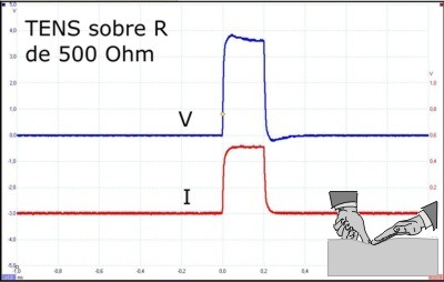
Fig 12.-- TENS over 500 Ohm.
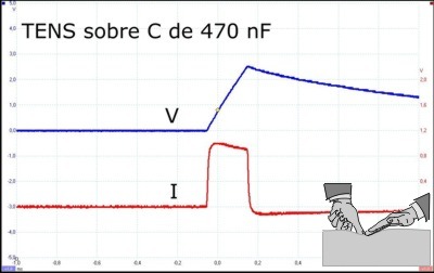
Fig 13.-- TENS over C of 470 nF.
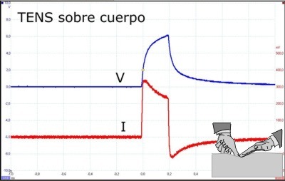
Fig 14.-- TENS on human body.
Responding to the comment that: "the intensity line in figure 11 is very thick and may represent current flow"; This is because the oscilloscope automatically goes to maximum sensitivity and the probe picks up environmental interference. This can be avoided by taking the oscilloscope out of automatic sensitivity and setting a fixed range of lower sensitivity, but if this range is too high, if there are weak waveforms, they may not be drawn. It is better to leave it on automatic even if you draw a dirty straight line or "with beards", as they say in electronic jargon.
If you test a probe in the air and the oscilloscope at maximum
sensitivity, you will see how many environmental interferences of a
multitude of frequencies appear on the screen, although an alternating
frequency of 50 or 60 Hz corresponding to the electrical network
predominates.
Posted on 06/03/2021